我现在正在RAID卡下配置2个PCIE
一个x16,一个x8,其中
x16→hilink7,8,10
x8→hilink5
配置相关见附件,按照BCU→IEU配置,并且修改了PSR文件
现在os下执行dmidecode –type 9,结果如下,x8对应的信息显示为x2,并且GPU卡没有插入,Current Usage为In Use
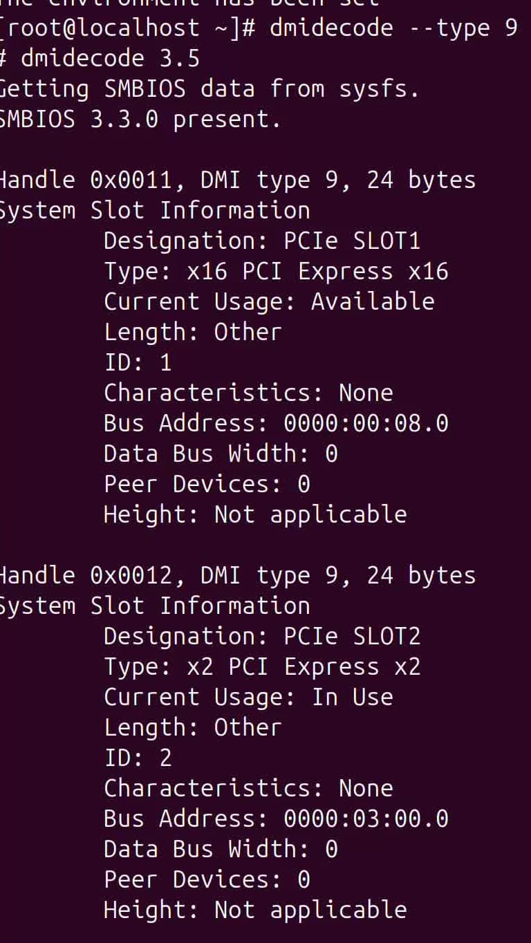
如何排查更改
我现在正在RAID卡下配置2个PCIE
一个x16,一个x8,其中
x16→hilink7,8,10
x8→hilink5
配置相关见附件,按照BCU→IEU配置,并且修改了PSR文件
现在os下执行dmidecode –type 9,结果如下,x8对应的信息显示为x2,并且GPU卡没有插入,Current Usage为In Use
如何排查更改
PSR更改:
    "UnitConfiguration_IEU2": {
        "SlotType": "IEU",
        "SlotNumber": 2,
        "SlotSilkText": "IEUSlot2",
        "Configurations": [
            {
                "UID": "00000001040302023940",
                "Index": 1,
                "SrcPortName": [
                    "A2a"
                ],
                "TargetPortID": [
                    60
                ],
                "Slot": [
                    2
                ],
                "Device": []
            }
      ],
        "Port1LinkInfo": ""
    },
BCU更改:
“BusinessConnector_CPU1UBC2”: {
“Name”: “BusinessConnector_CPU1UBC2”,
“Direction”: “Downstream”,
“BCUIndex”: “${Slot}”,
“Slot”: 2,
“LinkWidth”: “X8”,
“MaxLinkRate”: “PCIe 4.0”,
“ConnectorType”: “UBC”,
“SilkText”: “CPU1 UBC2”,
“UpstreamResources”: [
{
“Name”: “SerDes_0_5”,
“ID”: 1,
“Offset”: 0,
“Width”: 8
}
],
“Ports”: [
{
“Name”: “A2a”,
“ID”: 1,
“Offset”: 0,
“Width”: 8
}
],
“Port1LinkInfo”: “”,
“Port2LinkInfo”: “”
},
    "SerDes_0_5": {
        "Name": "SerDes_0_5",
        "ID": 5,
        "SocketID": 0,
        "LinkWidth": 8,
        "WorkMode": 1,
        "ModeConfigs": [
            {
                "Mode": 1,
                "Device": [
                    0,
                    0,
                    1,
                    1,
                    2,
                    2,
                    3,
                    3
                ],
                "ControllerIndex": [
                    0,
                    0,
                    0,
                    0,
                    0,
                    0,
                    0,
                    0
                ]
            },
            {
                "Mode": 4,
                "Device": [
                    4,
                    4,
                    4,
                    4,
                    4,
                    4,
                    4,
                    4
                ],
                "ControllerIndex": [
                    1,
                    1,
                    1,
                    1,
                    1,
                    1,
                    1,
                    1
                ]
            }
        ]
    },
RAID卡添加:
    "Connector_PCIe_2": {
        "Bom": "14140130",
        "Slot": 2,
        "Position": 2,
        "Presence": 1,
        "Id": "",
        "AuxId": "",
        "Buses": [
            "I2cMux_9545Chan3"
        ],
        "SystemId": "${SystemId}",
        "ManagerId": "${ManagerId}",
        "ChassisId": "${ChassisId}",
        "SilkText": "RiserCard${Slot}",
        "IdentifyMode": 2,
        "Container": "Component_RiserCard",
        "Type": "PCIe"
    },
    "BusinessConnector_3": {
        "Name": "Up_2",
        "Direction": "Upstream",
        "Slot": 2,
        "LinkWidth": "X8",
        "MaxLinkRate": "PCIe 4.0",
        "ConnectorType": "UBC",
        "Ports": [
            {
                "Name": "Down_2",
                "ID": 60,
                "Offset": 0,
                "Width": 8
            }
        ]
    },
    "BusinessConnector_4": {
        "Name": "Down_2",
        "Direction": "Downstream",
        "Slot": 2,
        "LinkWidth": "X8",
        "MaxLinkRate": "PCIe 4.0",
        "ConnectorType": "PCIe CEM",
        "UpstreamResources": [
            {
                "Name": "Up_2",
                "ID": 255,
                "Offset": 0,
                "Width": 8
            }
        ],
        "RefMgmtConnector": "#/Connector_PCIe_2",
        "RefPCIeAddrInfo": "#/PcieAddrInfo_2"
    },
    "PcieAddrInfo_2": {
        "Segment": 0,
        "SlotID": 2,
        "GroupID": 1,
        "PortID": 2,
        "SocketID": 0,
        "Bus": 5,
        "Device": 0,
        "Function": 0,
        "Location": "RiserCard${Slot}",
        "ComponentType": 8,
        "ContainerSlot": "${Slot}",
        "ContainerUID": "00000001040302023940",
        "ContainerUnitType": "IEU",
        "GroupPosition": "PcieAddrInfo_1_${GroupPosition}"
    },
按道理os下查询slot2应该是我配置的05:00.0,但是目前一直为03:00.0
x16也是类似配置,可以正常识别GPU卡
为啥raid卡可以接pcie卡?
RISER卡下挂载Pca9545_IEU芯片,然后扩展2条I2C通道用来接PCIE卡
答案内容由AI生成,仅供参考:
当前
dmidecode显示 x8 槽为 x2 且 Usage=In Use 的根本原因很可能是:
- CSR 配置中
LinkWidth错误地设置为了 X2;- 或 HiLink 资源不足导致链路协商失败降级;
- Presence 被硬编码为 1,导致即使无设备也显示“已使用”。
![]() 立即操作:
立即操作:
.sr 文件中对应的 LinkWidth 为 X8;Presence 为表达式或留空;dmidecode -type 9 查看是否修复。如仍有问题,请提供以下信息以便深入分析:
.sr 文件片段(含 BusinessConnector 和 Connector 定义);app.log 中关于 PCIeCard 加载的日志;dmesg | grep -i pcie 输出结果。在您描述的场景中,您正在通过 RAID卡配置两个PCIe卡(一个x16、一个x8),并已完成从BCU到IEU的相关CSR拓扑配置和PSR文件修改。但在OS中执行 dmidecode -type 9 时发现:
Current Usage 为 In Use,但实际并未插入GPU卡;拓扑结构:
.sr 文件并通过 IdentifyMode=2 配置。OS反馈异常:
Type: x2 PCI Express x2    # 应为 x8,实际被识别成 x2
Current Usage: In Use      # 无设备插入却被标记为“已使用”
可能原因来源:
LinkWidth 或能力描述错误;BusinessConnector 或 Connector_PCIe_X确保相关连接器中 LinkWidth 正确设定为 X8/X16。
"BusinessConnector_X": {
    "LinkWidth": "X8",
    "MaxLinkRate": "PCIe 4.0",
    "ConnectorType": "PCIe CEM"
}
错误示例:若此处误设为
"X2",则OS会严格按照此值生成DMI信息。
![]() 检查方式:
检查方式:
14140130_xxxx.sr);BusinessConnector 或 Connector_PCIE_SLOTX;LinkWidth 字段是否分别为 X16 和 X8。
提示:
LinkWidth决定DMI type 9 输出中的Type字段值。
您提到使用了 PcieAddrInfo,它是将物理槽位映射到逻辑总线的关键。
"PcieAddrInfo_2": {
    "ContainerSlot": "${Slot}",
    "Location": "PCIeSlot${Slot}"
}
请确认:
PcieAddrInfo_N;BusinessConnector 的 Slot 值一致;LinkWidth。![]() 验证命令(在BMC中):
验证命令(在BMC中):
busctl --user introspect bmc.kepler.hwdiscovery /bmc/kepler/Connector/Connector_PCIE_SLOT2_*
查看输出中的 LinkWidth 是否为 X8。
DMI Type 9 是由 BIOS 根据 BMC 提供的拓扑信息生成的,关键流程如下:
BMC (SR解析) → pcie_device组件 → 向BIOS上报Slot能力 → BIOS生成DMI表
/var/log/app.log 中是否有如下日志:[BizTopoLoader] Load PCIeCard, Slot=2, path=..., Id-AuxId=...
hwdiscovery NOTICE: load sr data successfully
PcieAddrInfo 是否包含 segment, bus, device, function 明确配置;bios_service.lua 能获取这些信息并通过 IPMI 传递给 BIOS。![]() 建议加日志:
建议加日志:
在 bios_service.lua 中打印 PCIe Slot 的 LinkWidth 和 Type,确认是否传递了正确值。
您配置了:
![]() 注意:HiLink 是高速串行通道,不可重复、不可错序使用。
注意:HiLink 是高速串行通道,不可重复、不可错序使用。
SerDes 到端口的映射?![]() 参考规则:
参考规则:
![]() 解决方案:
解决方案:
FirmwareRoute 检查路由是否冲突;dmesg | grep -i pcie 查看内核是否报告 link training failed。虽然未插入卡,却显示 Current Usage: In Use
Connector_PCIE_SLOT2 中配置了 'Presence': 1 或固定表达式;![]() 检查方法:
检查方法:
# 在BMC上查看该连接器状态
busctl call bmc.kepler.hwdiscovery bmc.kepler.Connector /bmc/kepler/Connector/Connector_PCIE_SLOT2_... Get y s bmc.kepler.Connector Present
如果返回 1,说明 BMC 告诉系统“卡在位”,BIOS 就会标记为 In Use。
![]() 处理方式:
处理方式:
'Presence': '<=/Scanner_Slot2.Value|>expr(...)'。有时旧的 DMI 缓存会影响结果。
否则
dmidecode会读取缓存的错误数据。
| 步骤 | 检查项 | 工具/命令 |
|---|---|---|
| 1 | CSR 中 LinkWidth 是否为 X8 / X16 |
查 .sr 文件 |
| 2 | Connector_PCIE_SLOTX 的 Id, AuxId, Presence 是否正确 |
busctl introspect |
| 3 | PcieAddrInfo 是否正确绑定槽位和总线 |
检查 JSON 结构 |
| 4 | BMC 日志是否加载 PCIe 卡成功 | grep PCIeCard /var/log/app.log |
| 5 | HiLink 分配是否足够且无冲突 | 查 CSR 中 FirmwareRoute |
| 6 | Current Usage: In Use 是否由 Presence 固定导致 |
查 Presence 配置 |
| 7 | OS 是否加载了过期 DMI 缓存 | 重启服务器彻底刷新 |
| 8 | 内核日志是否有 PCIe Link Training Fail | dmesg | grep -i failed|train |
# 在您的 .sr 文件中修正 LinkWidth
"BusinessConnector_2": {
    "LinkWidth": "X8",         # 不要写成 X2!
    "MaxLinkRate": "PCIe 4.0",
    "ConnectorType": "PCIe CEM"
}
同时确保:
.sr 文件至 /opt/bmc/sr/;搜索结果[5]:[RAID卡适配指导] 强调 BIOS 上报 BDF 后 BMC 加载 CSR,需保证 Id/AuxId 正确。搜索结果[4]:[板卡适配指南] 指出非天池组件需通过 Id + AuxId 匹配 .sr 文件。Entity: PCIeAddrInfo:明确其作用是同步 SlotId、SocketId、BDF 等信息用于拓扑建立。Document Chunk 2:描述了类似问题,pcie_device 中 slot/socket 显示为0,源于同步失败。当前
dmidecode显示 x8 槽为 x2 且 Usage=In Use 的根本原因很可能是:
- CSR 配置中
LinkWidth错误地设置为了 X2;- 或 HiLink 资源不足导致链路协商失败降级;
- Presence 被硬编码为 1,导致即使无设备也显示“已使用”。
![]() 立即操作:
立即操作:
.sr 文件中对应的 LinkWidth 为 X8;Presence 为表达式或留空;dmidecode -type 9 查看是否修复。如仍有问题,请提供以下信息以便深入分析:
.sr 文件片段(含 BusinessConnector 和 Connector 定义);app.log 中关于 PCIeCard 加载的日志;dmesg | grep -i pcie 输出结果。需要我帮您审查具体的 .sr 配置内容吗?欢迎贴出相关片段。
您好,这边为什么要改BCU上的sr呢?一般来说BCU上一个固定UBC/UBCDD端口连接的资源(hilink)是确定的。这边是对BCU硬件做了修改吗?
如果要配置riser卡,需要您那边的硬件去给一个槽位的预期,说明这个槽位预期的lane口和SlotId,您可以将得到的值和一键收集下的AppDump/Bios/1/SilkConfig.json中的PCIe中的具体丝印比对,应该会有一个条目的Lane和SlotId和硬件的预期一致。
我们这边硬件使用了Hilink5+6接x16的GPU,我这边使用华为标准920l的BCU库里面,没有关于Hilink5+6的配置,所以需要更改。
目前已经解决了slot2槽位,Bus Address问题,将PcieAddrInfo_2里面的“PortID”:改为实际的
目前测试下来,A3a,A3c这种似乎与SerDes没有很明显的关联,我改为A4a也可以正常显示PCIE卡
如果不走拓扑建立流程,只需要配置PcieAddrInfo里的PortID和SlotID信息bios侧就能完成识别。
A3a、A3c这种是和具体的SerDes对应的,只是在不走拓扑建立的时候不感知这些,一般只有配在IEU、SEU这种才需要拓扑建立。
您是在哪里改A4a的呢?是在UBCDD_CPU1这种对象里吗?
我这边是在PSR中更改SrcPortName,TargetPortID,然后BCU里面对应SrcPortName,IEU里面对应TargetPortID
PSR:
            {
                "UID": "00000001040302023940",
                "Index": 2,
                "SrcPortName": [
                    "A4a"
                ],
                "TargetPortID": [
                    48
                ],
                "Slot": [
                    2
                ],
                "Device": []
            }
      ],
        "Port1LinkInfo": ""
    },
BCU:
    "BusinessConnector_CPU1UBC2": {
        "Name": "BusinessConnector_CPU1UBC2",
        "Direction": "Downstream",
        "BCUIndex": "${Slot}",
        "Slot": 2,
        "LinkWidth": "X8",
        "MaxLinkRate": "PCIe 4.0",
        "ConnectorType": "UBC",
        "SilkText": "CPU1 UBC2",
        "UpstreamResources": [
            {
                "Name": "SerDes_0_5",
                "ID": 2,
                "Offset": 0,
                "Width": 8
            }
        ],
        "Ports": [
            {
                "Name": "A4a",
                "ID": 2,
                "Offset": 0,
                "Width": 8
            }
        ],
        "Port1LinkInfo": "",
        "Port2LinkInfo": ""
    },
riser:
"Connector_PCIe_2": {
        "Bom": "14140130",
        "Slot": 2,
        "Position": 2,
        "Presence": 1,
        "Id": "",
        "AuxId": "",
        "Buses": [
            "I2cMux_9545Chan3"
        ],
        "SystemId": "${SystemId}",
        "ManagerId": "${ManagerId}",
        "ChassisId": "${ChassisId}",
        "SilkText": "RiserCard${Slot}",
        "IdentifyMode": 2,
        "Container": "Component_RiserCard",
        "Type": "PCIe"
    },
    "BusinessConnector_3": {
        "Name": "Up_2",
        "Direction": "Upstream",
        "Slot": 2,
        "LinkWidth": "X8",
        "MaxLinkRate": "PCIe 4.0",
        "ConnectorType": "UBC",
        "Ports": [
            {
                "Name": "Down_2",
                "ID": 48,
                "Offset": 0,
                "Width": 8
            }
        ]
    },
    "BusinessConnector_4": {
        "Name": "Down_2",
        "Direction": "Downstream",
        "Slot": 2,
        "LinkWidth": "X8",
        "MaxLinkRate": "PCIe 4.0",
        "ConnectorType": "PCIe CEM",
        "UpstreamResources": [
            {
                "Name": "Up_2",
                "ID": 255,
                "Offset": 0,
                "Width": 8
            }
        ],
        "RefMgmtConnector": "#/Connector_PCIe_2",
        "RefPCIeAddrInfo": "#/PcieAddrInfo_2"
    },
    "PcieAddrInfo_2": {
        "Segment": 0,
        "SlotID": 2,
        "GroupID": 2,
        "PortID": 4,
        "SocketID": 0,
        "Bus": 5,
        "Device": 0,
        "Function": 0,
        "Location": "RiserCard${Slot}",
        "ComponentType": 8,
        "ContainerSlot": "${Slot}",
        "ContainerUID": "00000001040302023940",
        "ContainerUnitType": "IEU",
        "GroupPosition": "PcieAddrInfo_2_${GroupPosition}"
    },
通过这个id 48可以找到白名单上的A4a,再找到BCU的SerDes_0_5,您可以对比一下PcieAddrInfo上的PortId和SerDes_0_5 中Device的最低位是否一致,如果一致就是拓扑建立已经完成了
你好,请教下,我这边有一个PCIe设备是从CPU卡上的SerDes直接接出来的(HIlink5 X8,被一分为二,两个X4,下面接了两个X4的PCIe设备),我怎么确定它们的PortID和SLotID呀,这个能在CPU侧通过什么工具读出来吗?
在web页面中能是识别到我的PCIe设备,但是BDF信息那些是不正常的。相关配置如下,
“SerDes_0_5”: {
“Name”: “SerDes_0_5”,
“ID”: 5,
“SocketID”: 0,
“LinkWidth”: 8,
“WorkMode”: 1,
“ModeConfigs”: [
{
“Mode”: 1,
“Device”: [
0,
0,
0,
0,
2,
2,
2,
2
],
“ControllerIndex”: [
0,
0,
0,
0,
0,
0,
0,
0
]
}
]
},
“BusinessConnector_2”: {
“Name”: “Down_2”,
“Direction”: “Downstream”,
“Slot”: 2,
“LinkWidth”: “X4”,
“MaxLinkRate”: “PCIe 2.0”,
“ConnectorType”: “PCIe CEM”,
“UpstreamResources”: [
{
“Name”: “SerDes_0_5”,
“ID”: 5,
“Offset”: 4,
“Width”: 4
}
],
“RefMgmtConnector”: “#/Connector_NIC_1”,
“RefPCIeAddrInfo”: “#/PcieAddrInfo_NIC_1”
},
“Connector_NIC_1”: {
“Buses”: [
“I2c_7”
],
“Bom”: “14140130”,
“Slot”: 2,
“Position”: 2,
“Presence”: 1,
“Id”: “8088010b”,
“AuxId”: “80880102”,
“IdentifyMode”: 2,
“SystemId”: 1,
“SilkText”: “BCU”,
“Container”: “Component_Pcie”,
“Type”: “PCIe”
},
“PcieAddrInfo_NIC_1”: {
“Segment”: 0,
“GroupID”: 1,
“SocketID”: 0,
“SlotID”: 2,
“PortID”: 2,
“Bus”: 2,
“Device”: 0,
“Function”: 0,
“Location”: “BCU${Slot}”,
“ComponentType”: 8,
“ControllerIndex”: 0,
“ControllerType”: 1,
“ContainerSlot”: “${Slot}”,
“ContainerUID”: “00000001020302071127”,
“ContainerUnitType”: “BCU”,
“GroupPosition”: “PcieAddrInfo_NIC_1_${GroupPosition}”
},
能否帮忙确认下这个sr的配置有啥问题吗?
在没有硬件给的表的情况下我们这边也没法确定它应该关联到什么portID,不过理论上关联的PortID只和插哪根UBCDD线有关系,可以看一下插同样的线的IEU设备对应的Addr关联哪个PortID。
PortID和rootBDF在带内有一张对应的表,PSR里也有对应的配置,可以从实际带内加载的rootBDF往回找看看。